1. FireSim Basics
FireSim is a cycle-accurate, FPGA-accelerated scale-out computer system simulation platform developed in the Berkeley Architecture Research Group in the EECS Department at the University of California, Berkeley.
FireSim is capable of simulating from one to thousands of multi-core compute nodes, derived from silicon-proven and open target-RTL, with an optional cycle-accurate network simulation tying them together. FireSim runs on FPGAs in public cloud environments like AWS EC2 F1, removing the high capex traditionally involved in large-scale FPGA-based simulation.
FireSim is useful both for datacenter architecture research as well as running many single-node architectural experiments in parallel on FPGAs. By harnessing a standardized host platform and providing a large amount of automation/tooling, FireSim drastically simplifies the process of building and deploying large-scale FPGA-based hardware simulations.
To learn more, see the FireSim website and the FireSim ISCA 2018 paper.
For a two-minute overview that describes how FireSim simulates a datacenter, see our ISCA 2018 lightning talk on YouTube.
1.1. Two common use cases:
1.1.1. Single-Node Simulation, in Parallel
In this mode, FireSim allows for simulation of individual Rocket Chip-based nodes without a network, which allows individual simulations to run at ~150 MHz. The FireSim manager has the ability to automatically distribute jobs to many parallel simulations, expediting the process of running large workloads like SPEC. For example, users can run all of SPECInt2017 on Rocket Chip in ~1 day by running the 10 separate workloads in parallel on 10 FPGAs.
1.1.2. Datacenter/Cluster Simulation
In this mode, FireSim also models a cycle-accurate network with parameterizeable bandwidth and link latency, as well as configurable topology, to accurately model current and future datacenter-scale systems. For example, FireSim has been used to simulate 1024 quad-core Rocket Chip-based nodes, interconnected by a 200 Gbps, 2us network. To learn more about this use case, see our ISCA 2018 paper or two-minute lightning talk.
1.2. Other Use Cases
This release does not support a non-cycle-accurate network as our AWS Compute Blog Post/Demo used. This feature will be restored in a future release.
If you have other use-cases that we haven’t covered, feel free to contact us!
1.3. Background/Terminology
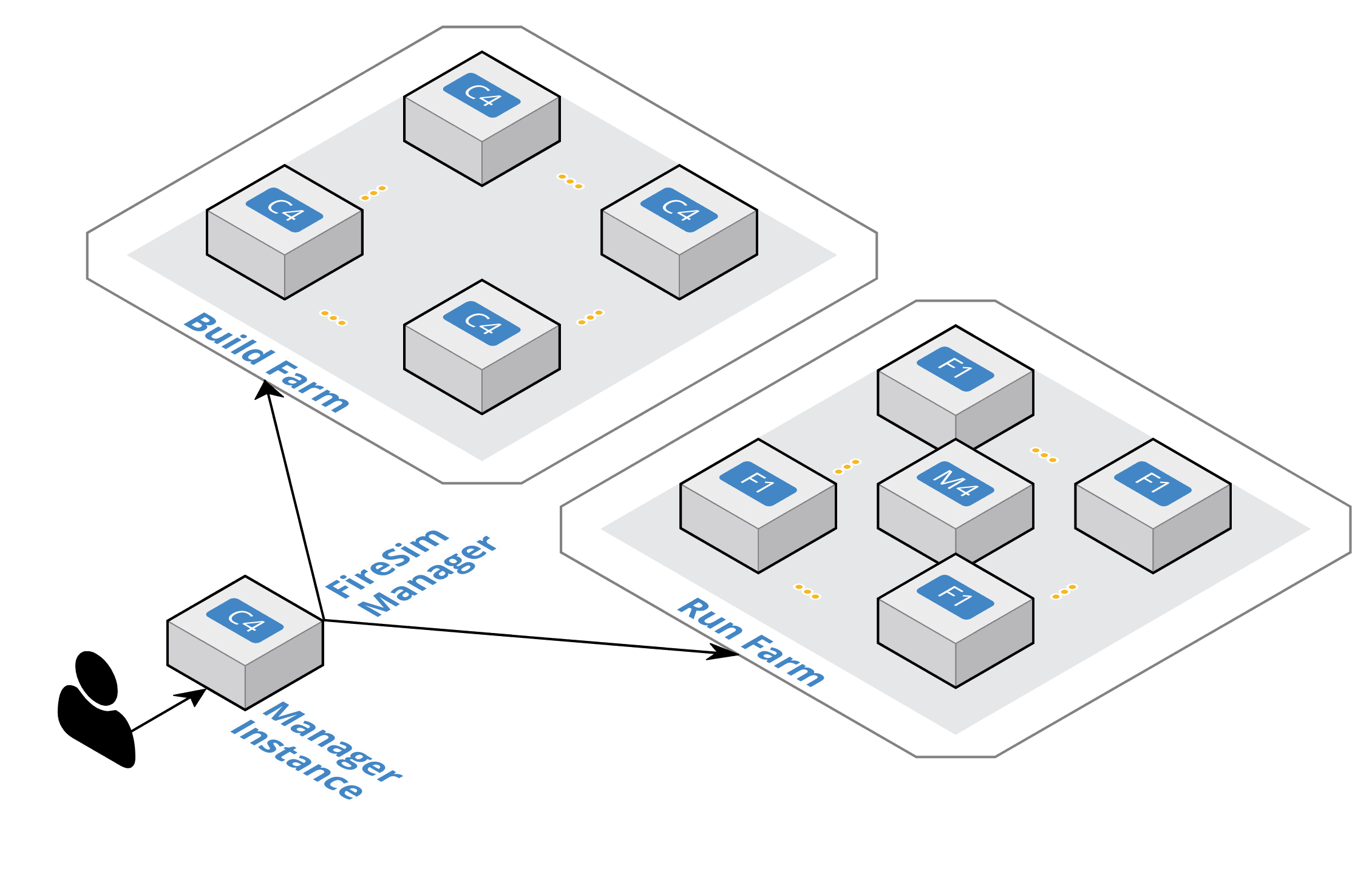
FireSim Infrastructure Diagram
- FireSim Manager (
firesim) - This program (available on your path as
firesimonce we source necessary scripts) automates the work required to launch FPGA builds and run simulations. Most users will only have to interact with the manager most of the time. If you’re familiar with tools like Vagrant or Docker, thefiresimcommand is just like thevagrantanddockercommands, but for FPGA simulators instead of VMs/containers. - Manager Instance
- This is the AWS EC2 instance that you will SSH-into and do work on. This is where you’ll clone your copy of FireSim and use the FireSim Manager to deploy builds/simulations from.
- Build Farm
- These are instances that are elastically started/terminated by the FireSim manager when you run FPGA builds. The manager will automatically ship source for builds to these instances and run the Verilog -> FPGA Image process on them.
- Run Farm
- These are a tagged collection of F1 (and M4) instances that the manager automatically launches and deploys simulations onto. You can launch multiple Run Farms in parallel, each with their own tag, to run multiple separate simulations in parallel.
To disambiguate between the computers being simulated and the computers doing the simulating, we also define:
- Target
- The design and environment under simulation. Generally, a group of one or more multi-core RISC-V microprocessors with or without a network between them.
- Host
- The computers executing the FireSim simulation – the Run Farm from above.
We frequently prefix words with these terms. For example, software can run on the simulated RISC-V system (target-software) or on a host x86 machine (host-software).
- Golden Gate (MIDAS II)
- The FIRRTL compiler used by FireSim to convert target RTL into a decoupled simulator. Formerly named MIDAS.
1.4. Using FireSim/The FireSim Workflow
The tutorials that follow this page will guide you through the complete flow for getting an example FireSim simulation up and running. At the end of this tutorial, you’ll have a simulation that simulates a single quad-core Rocket Chip-based node with a 4 MB last level cache, 16 GB DDR3, and no NIC. After this, you can continue to a tutorial that shows you how to simulate a globally-cycle-accurate cluster-scale FireSim simulation. The final tutorial will show you how to build your own FPGA images with customized hardware. After you complete these tutorials, you can look at the Advanced documentation in the sidebar to the left.
Here’s a high-level outline of what we’ll be doing in our tutorials:
- Initial Setup/Installation
- First-time AWS User Setup: You can skip this if you already have an AWS account/payment method set up.
- Configuring required AWS resources in your account: This sets up the appropriate VPCs/subnets/security groups required to run FireSim.
- Setting up a “Manager Instance” from which you will coordinate building and deploying simulations.
- Single-node simulation tutorial: This tutorial guides you through the process of running one simulation on a Run Farm consisting of a single
f1.2xlarge, using our pre-built public FireSim AGFIs. - Cluster simulation tutorial: This tutorial guides you through the process of running an 8-node cluster simulation on a Run Farm consisting of one
f1.16xlarge, using our pre-built public FireSim AGFIs and switch models. - Building your own hardware designs tutorial (Chisel to FPGA Image): This tutorial guides you through the full process of taking Rocket Chip RTL and any custom RTL plugged into Rocket Chip and producing a FireSim AGFI to plug into your simulations. This automatically runs Chisel elaboration, FAME-1 Transformation, and the Vivado FPGA flow.
Generally speaking, you only need to follow step 4 if you’re modifying Chisel RTL or changing non-runtime configurable hardware parameters.
Now, hit next to proceed with setup.